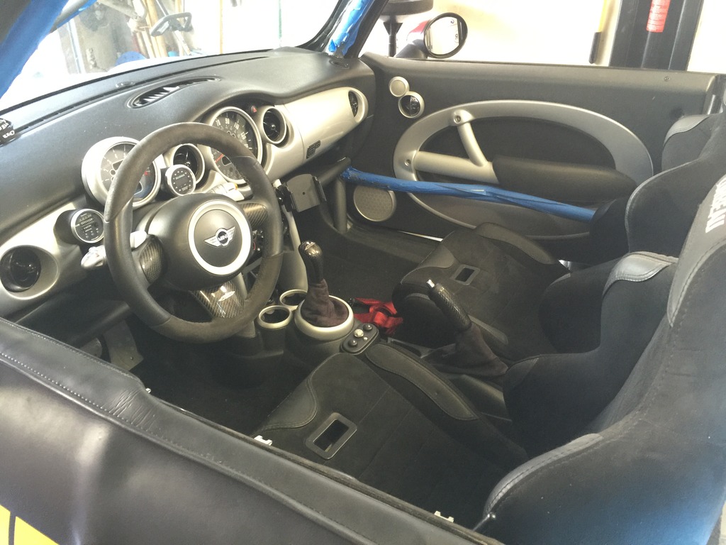
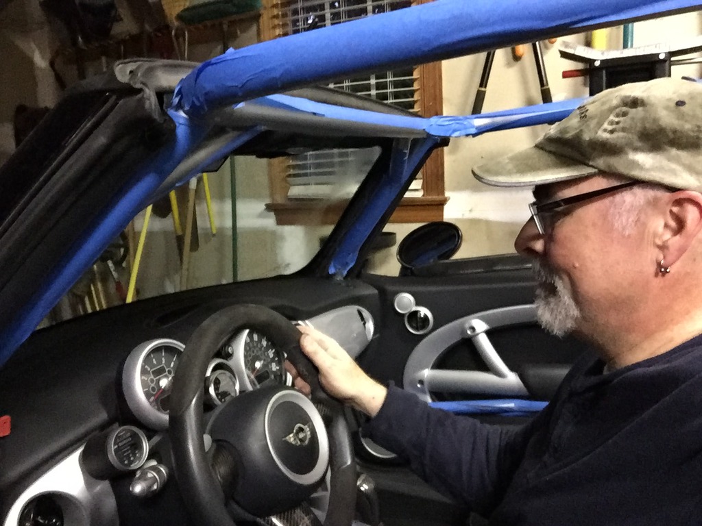
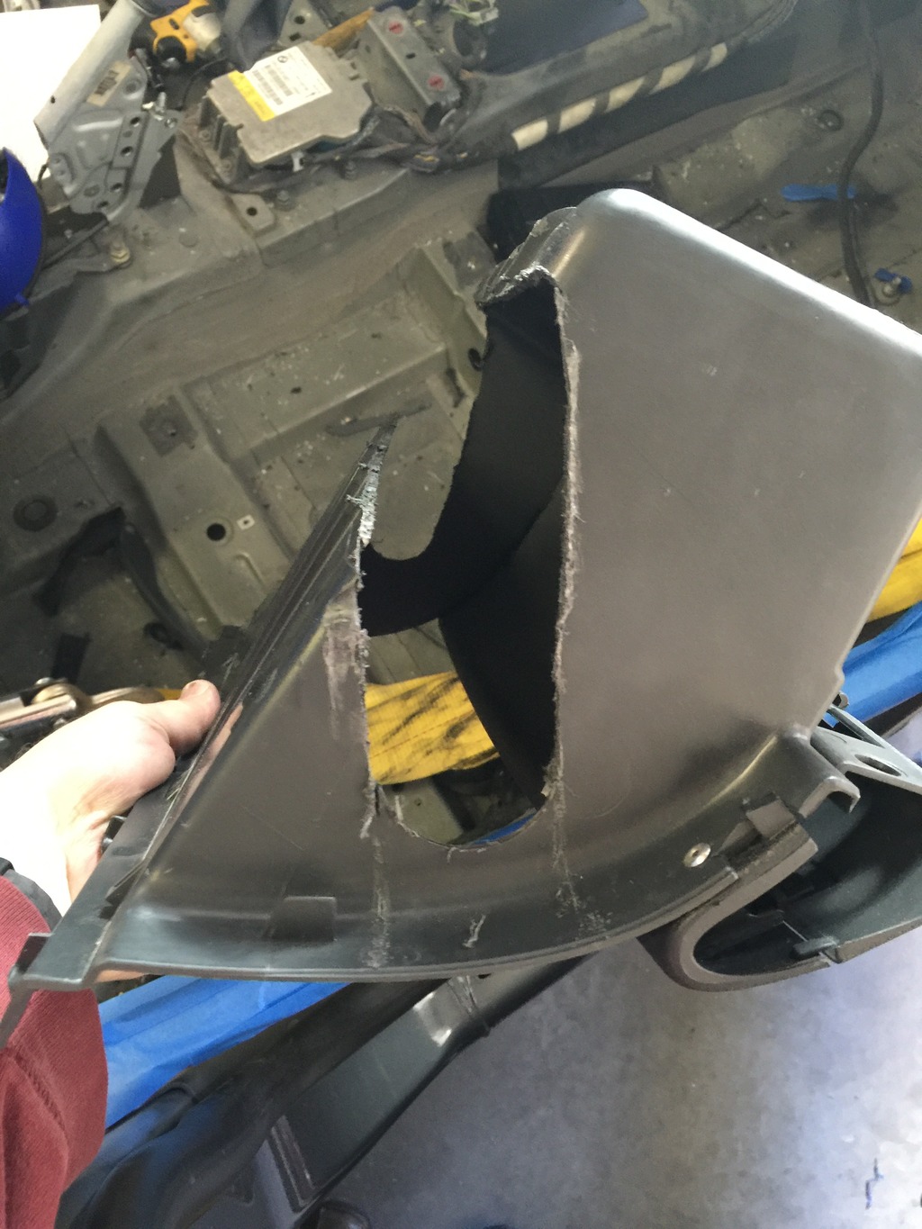
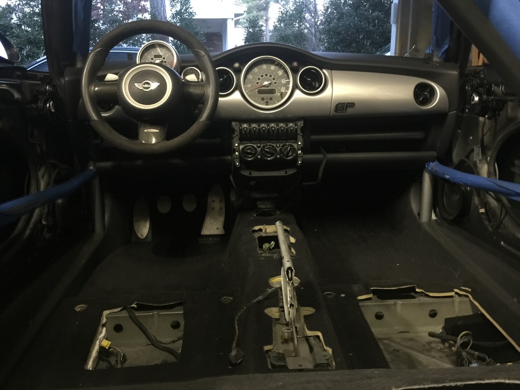
Front suspension

Today’s progress: got started on the front suspension.

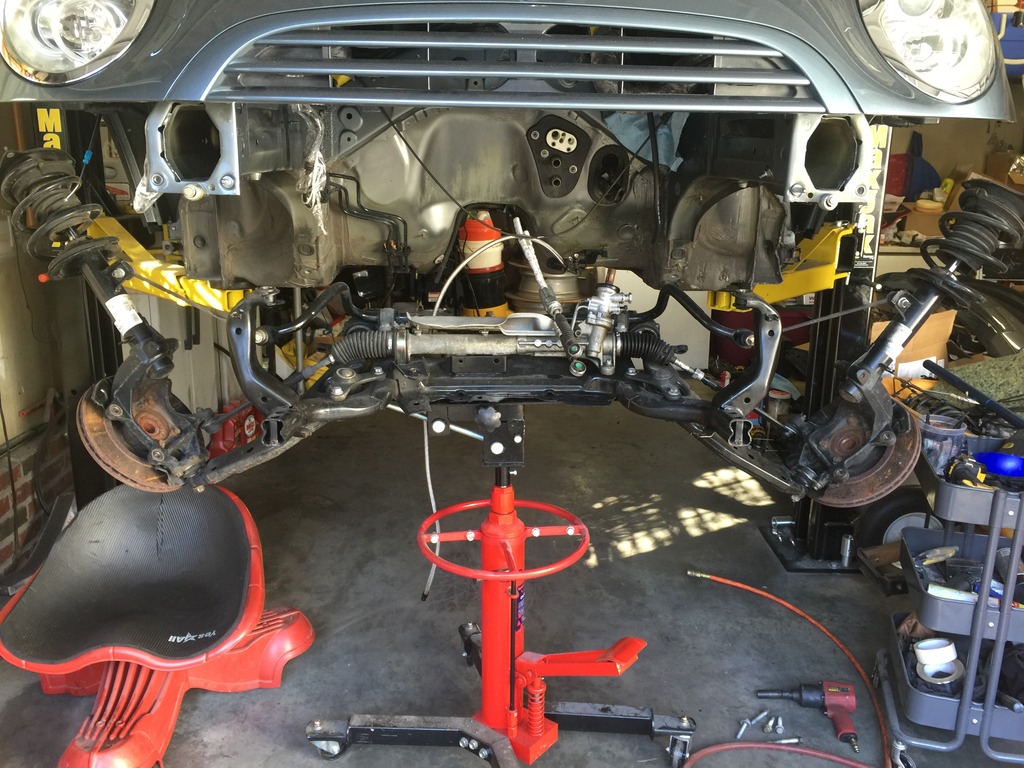
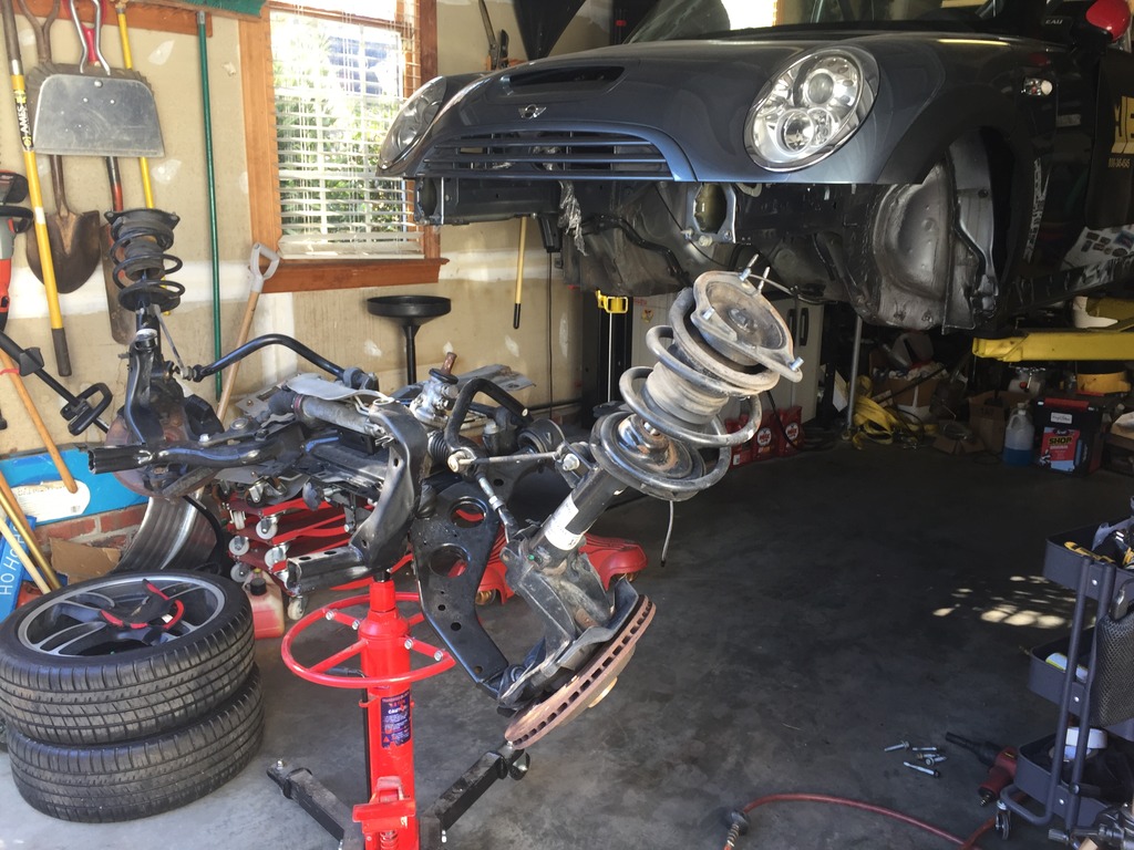
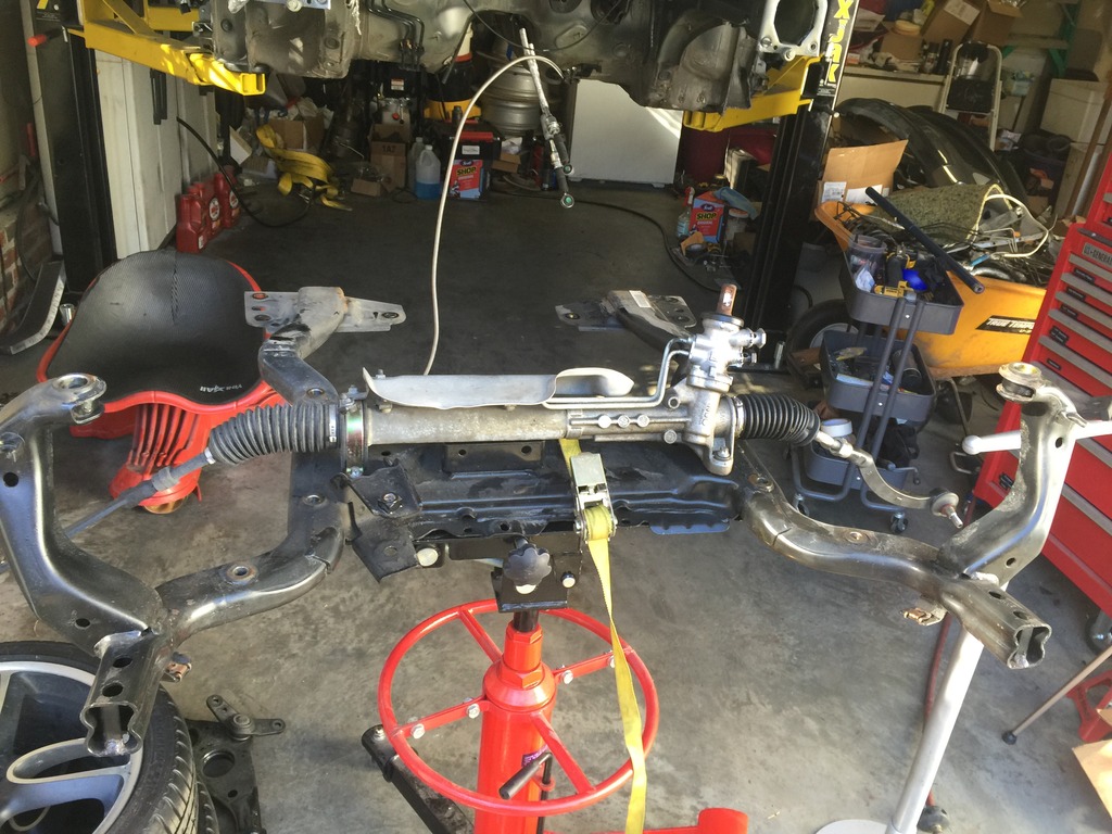
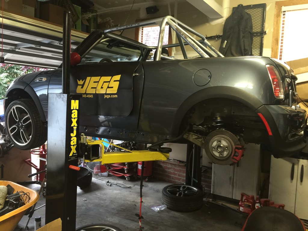
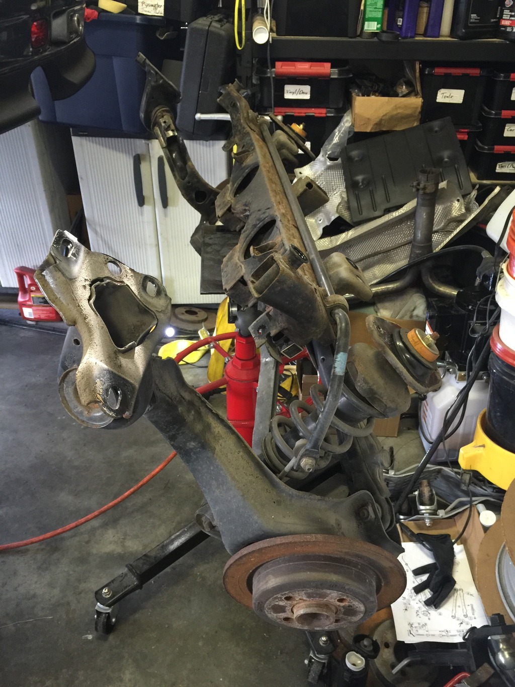
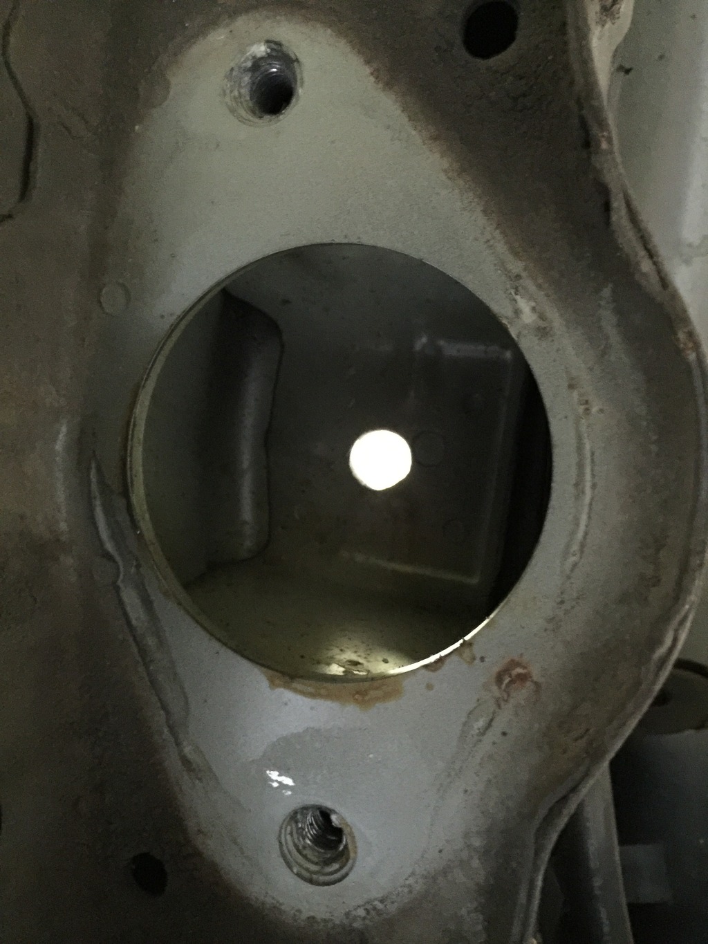
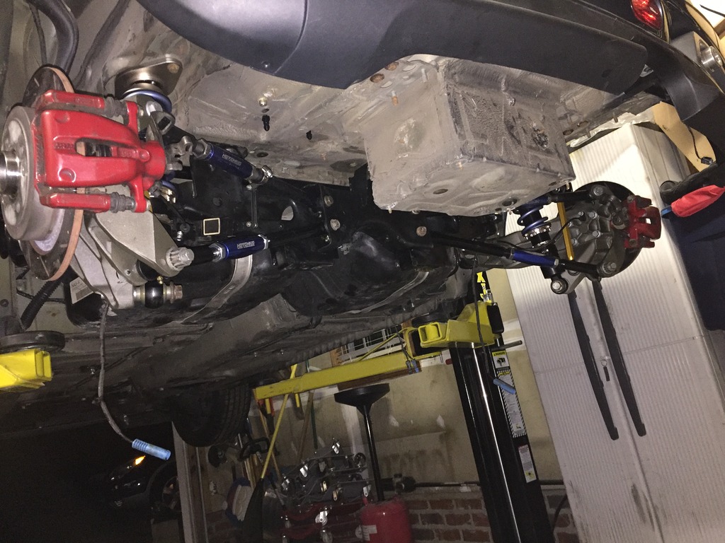
Dropped the front subframe. Yeah, lift and tall transmission jack come in handy. Dropped the whole thing intact in less than 10 minutes. 10 bolts + 6 nuts.
Click the image to open in full size.

Pulled it out and stripped everything off it. Cleaned up and treated some rust.
Click the image to open in full size.Click the image to open in full size.

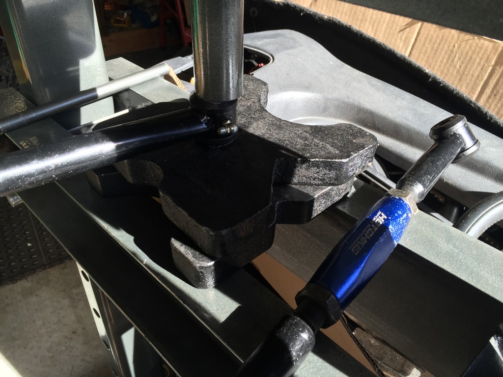
Pressed out my 100k mile old Powerflex purple bushings and pressed new Powerflex black bushings into the LCA brackets.

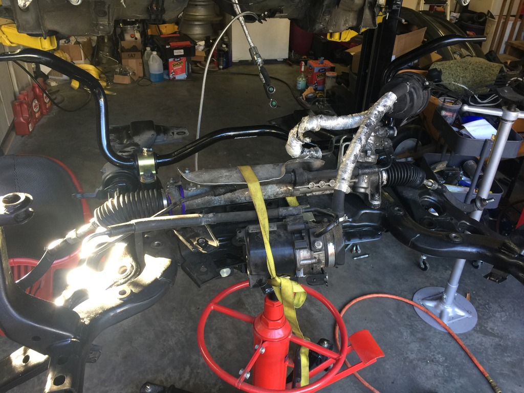
Installed new lower control arms (wishbones), the bushings, and Hotchkis sway bar.
Decided I needed new ball joints. Didn’t find any locally, so ordered a set. Will be delayed for a few days until they get here.

Pulled off the steering rack to save as a spare. Installed my old steering rack with pump and reservoir still attached. Used new Powerflex purple rack bushing. Installed two new tie rods.
Click the image to open in full size.

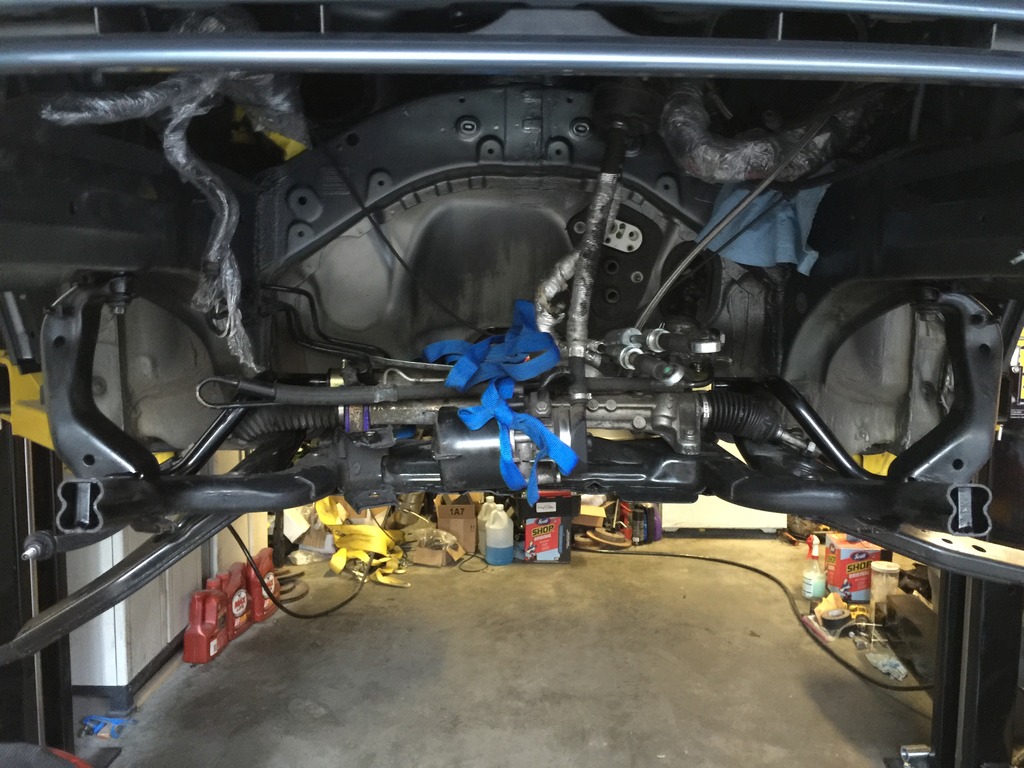
Maneuvered the subframe back into position, raised it, and popped in 10 bolts. Done. That jack is AWESOME.
Click the image to open in full size.

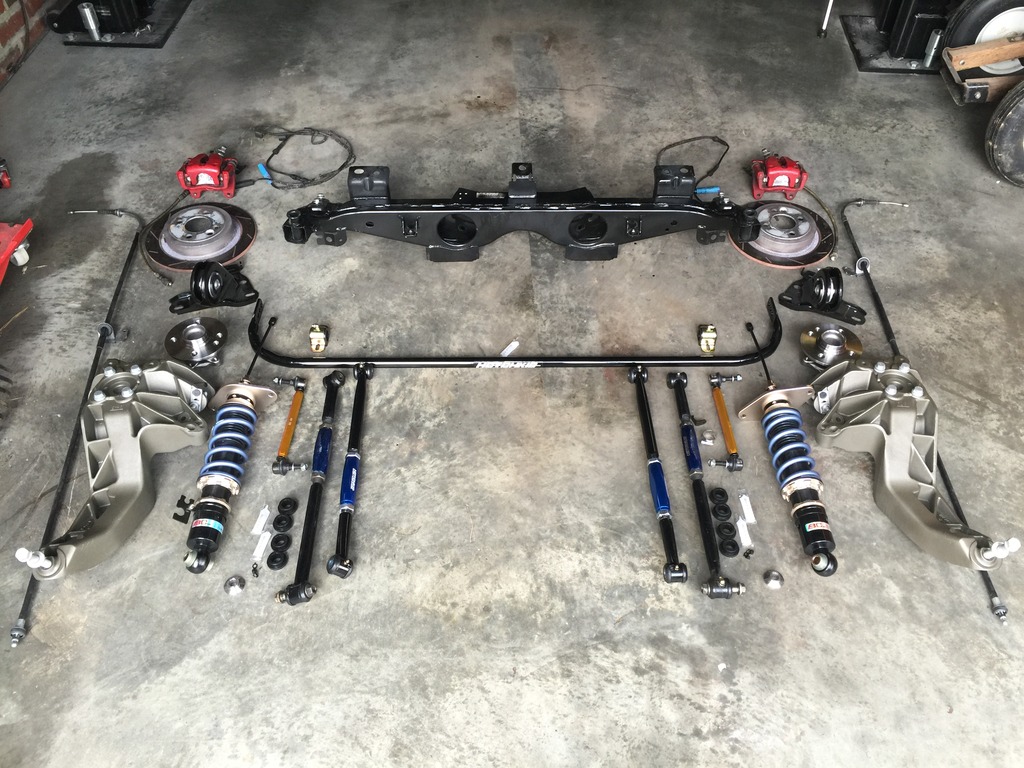
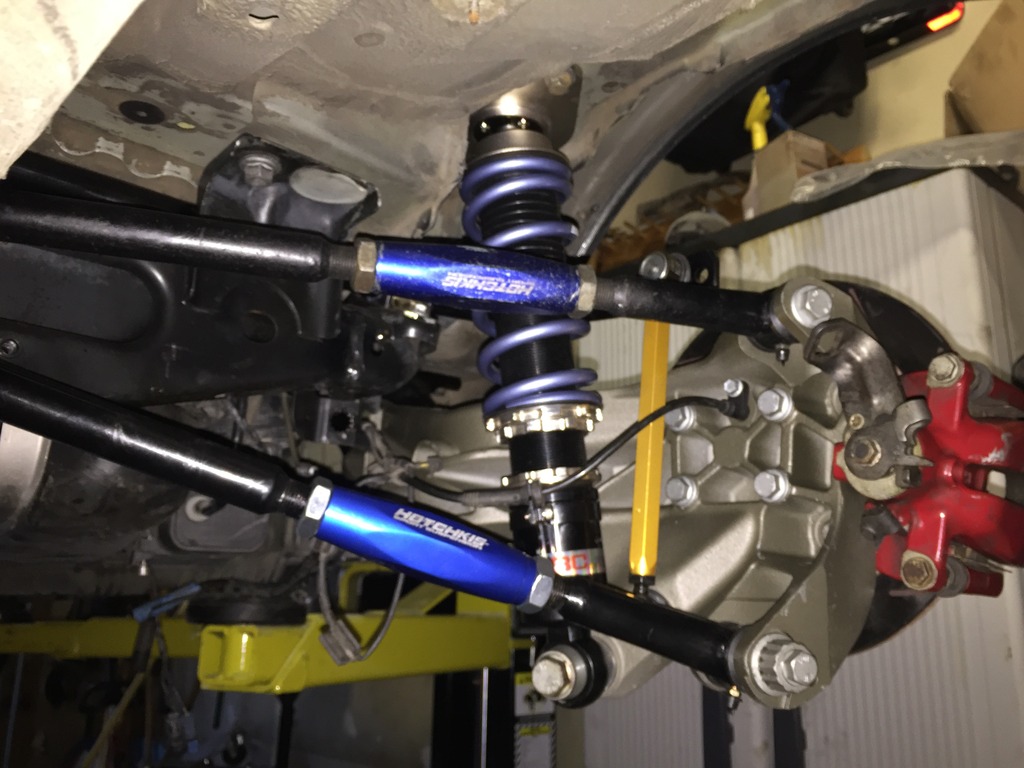
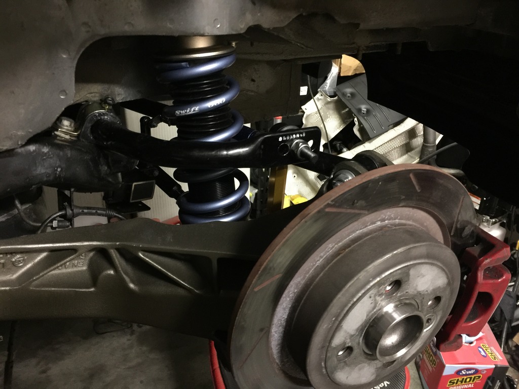
Rear suspension done

Rear stuff is DONE.

Porn:
Click the image to open in full size.

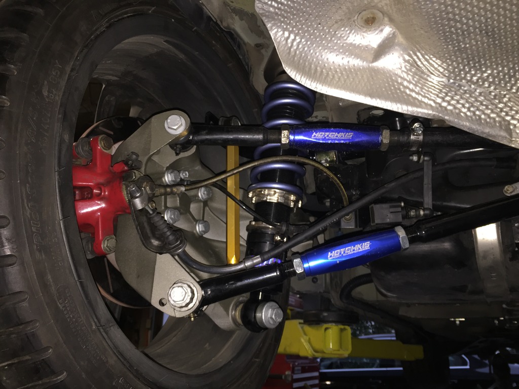
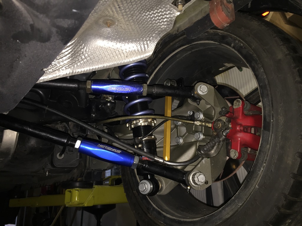
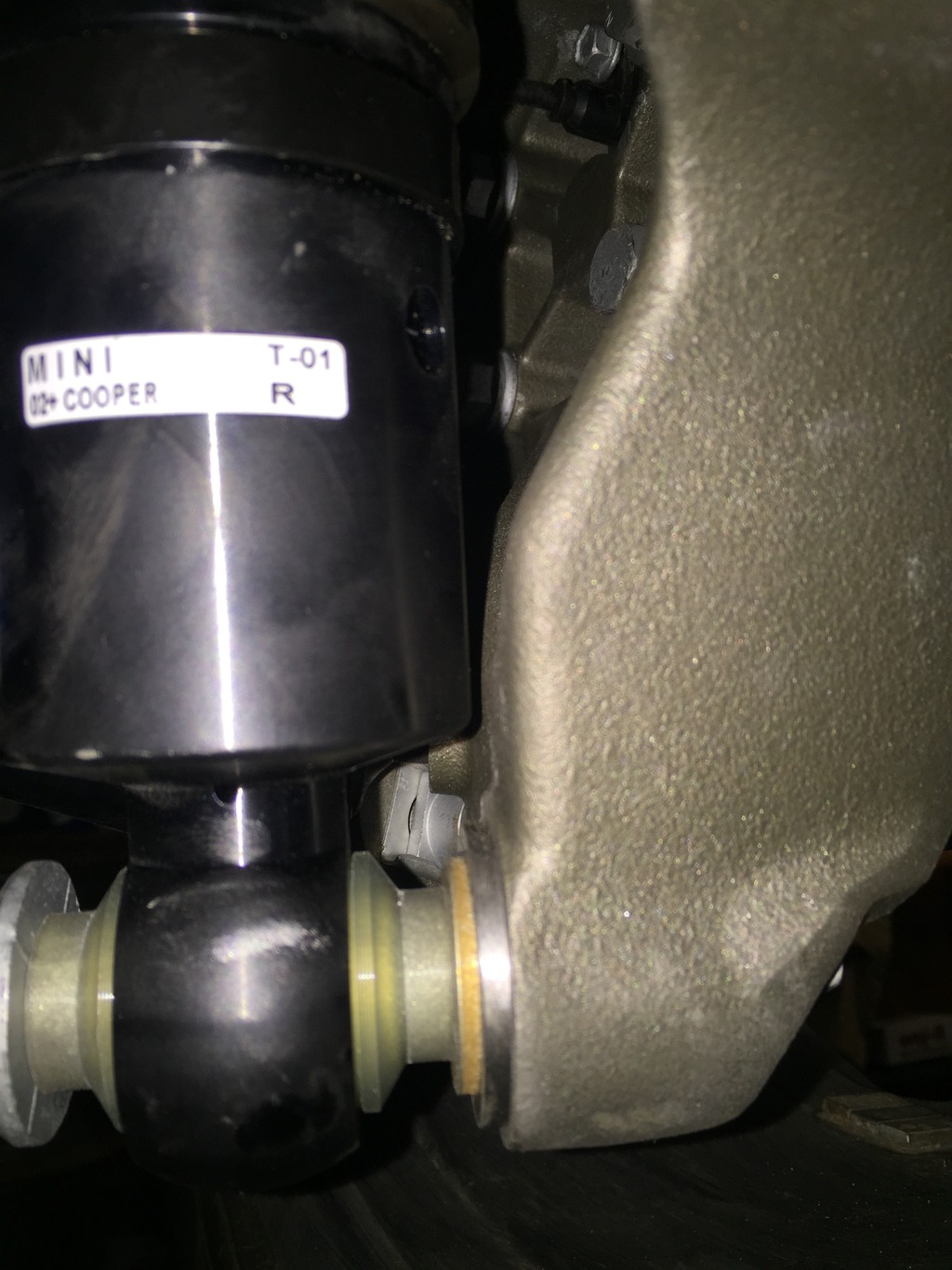
Added a hardened washer on each side as a shim between shock and control arm adapter, to get a couple extra mm of clearance between the shock body and the arm.
Click the image to open in full size.

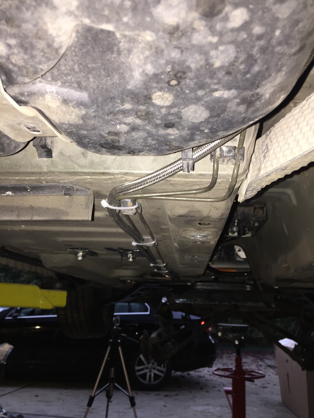
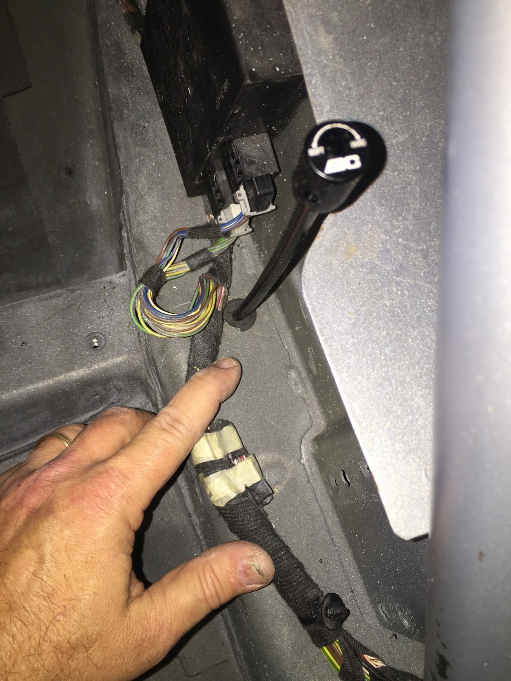
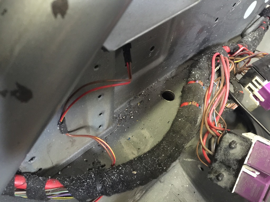
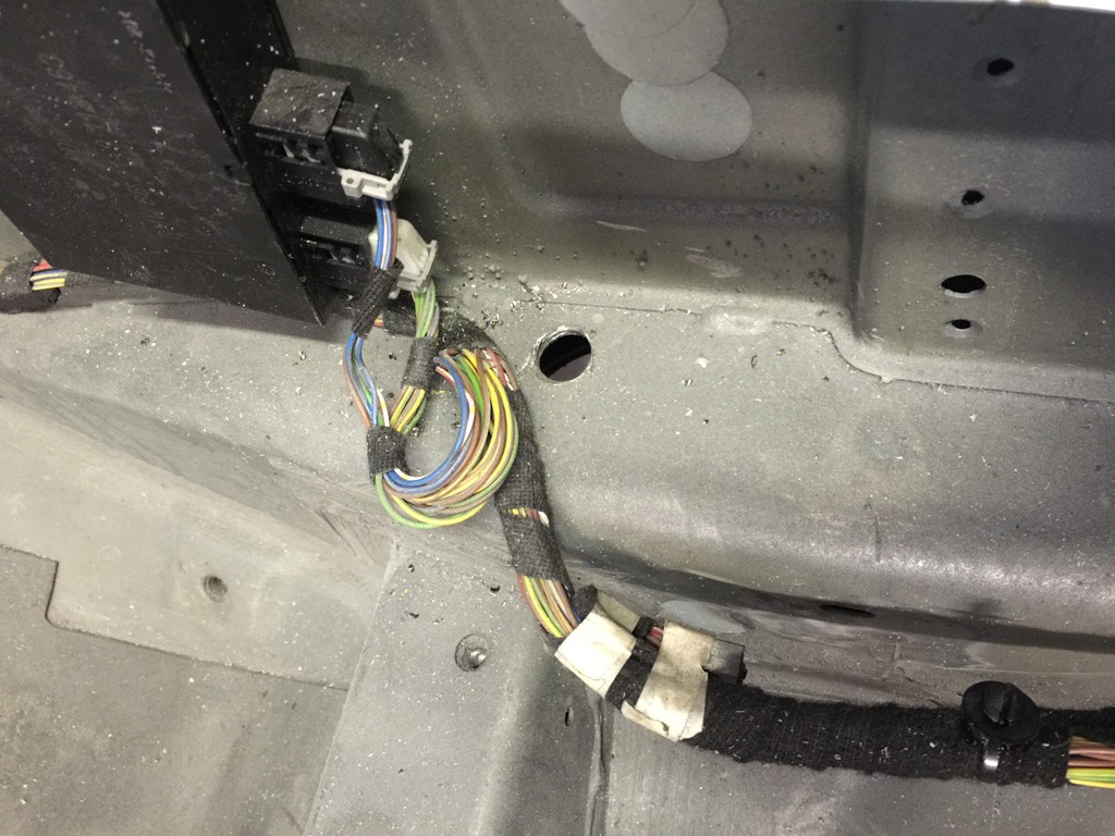
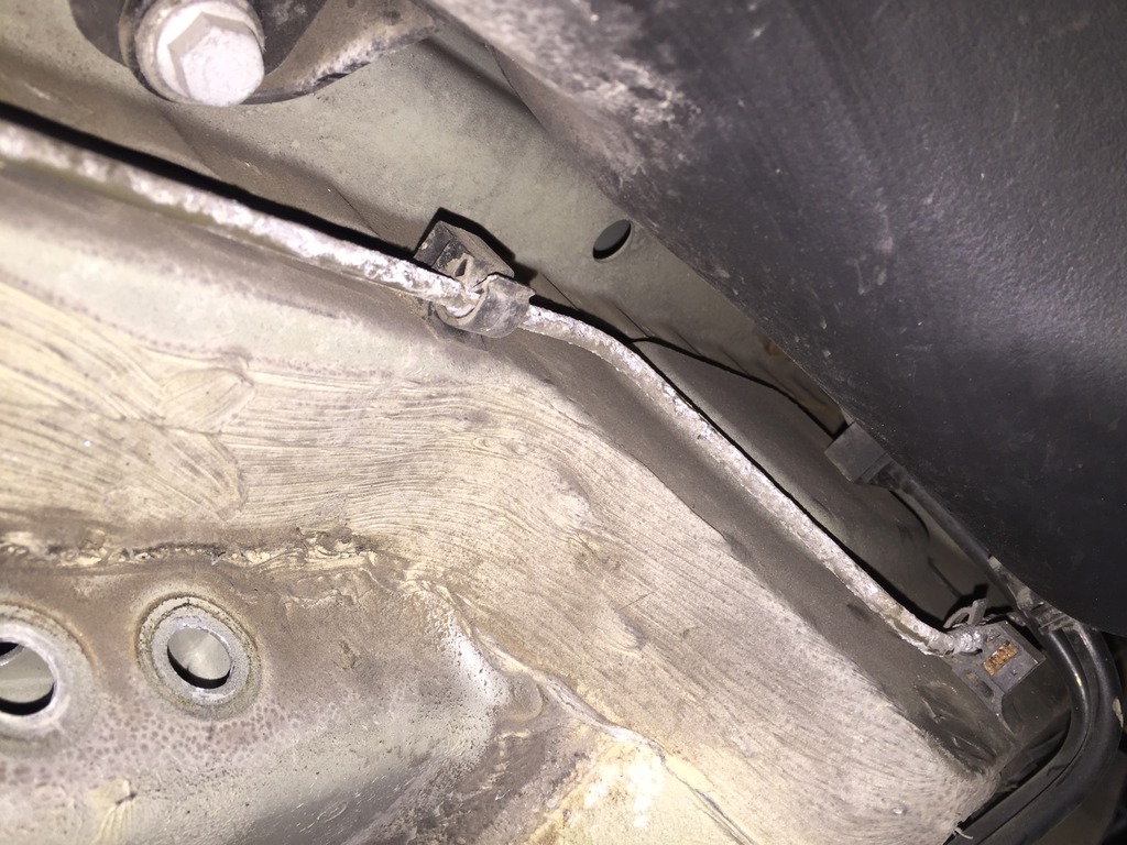
Cables, lines and sensors all connected. Just need to fill and bleed brakes later.

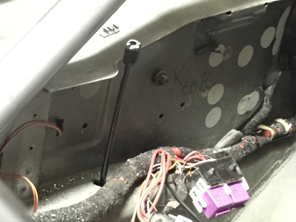
Also ran meth line from the boot to the front…
Click the image to open in full size.

Added rubber grommets in the adjuster holes…
Click the image to open in full size.

Will start on the front this weekend.

More important parts

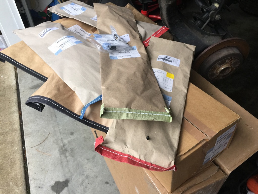
Another big box from Steven at eMINIparts!
Click the image to open in full size.

Looks pretty exciting, yes?

Well, it looks better on the car….
Click the image to open in full size.

All new arch trim. Took a few minutes out from working on work stuff, to snap it on. Huge improvement. Starting to look like a car…

Suspension Sunday!

Suspension Sunday!

Click the image to open in full size.

A bunch of parts:

  • Blimey/Locutus Mk1’s old rear subframe (with rust converted and painted), H-sport control arms, Gen2 JCW rear brakes/cables, sensors, and a bit of hardware
  • GP0769’s trailing arms, blasted and painted
  • New wheel bearings, front suspension pivots, and lots of hardware, from eMINIparts
  • A new pair of H-sport control arms and headlight leveler sensor attachment from Detroit Tuned
  • New custom-valved BC coilovers with adjusters and Swift springs, GP shock adapter bushings, and Whiteline end links, from Greene Performance
  • New 25mm Hotchkis comp sway bar from somewhere 🙂

First refreshed my old H-sport adjustable control arms, with new bushings. the old bushings were showing some age, after about 100k miles. Boy, a press comes in handy for stuff that calls for it.
Click the image to open in full size.

Then took a lot of pictures of the existing rear suspension, to ensure I could remember where everything went after I took it apart.

While looking at it, I concluded that it would be easiest to just drop it intact. I bought the high-lift transmission jack for just this kind of thing, after all. Determined that it’s only 5 bolts for the subframe, 4 bolts for the shocks, and 6 bolts for the front pivots… then it’s all free. The Harbor Freight Earthquake impact gun made quick work of a bunch of rusted bolts that had never been loosened before. Only took about 10 minutes, and it was off! It IS very heavy, don’t attempt to drop it intact without either a similar lift to hold it up, or a couple of strong friends.
Click the image to open in full size.

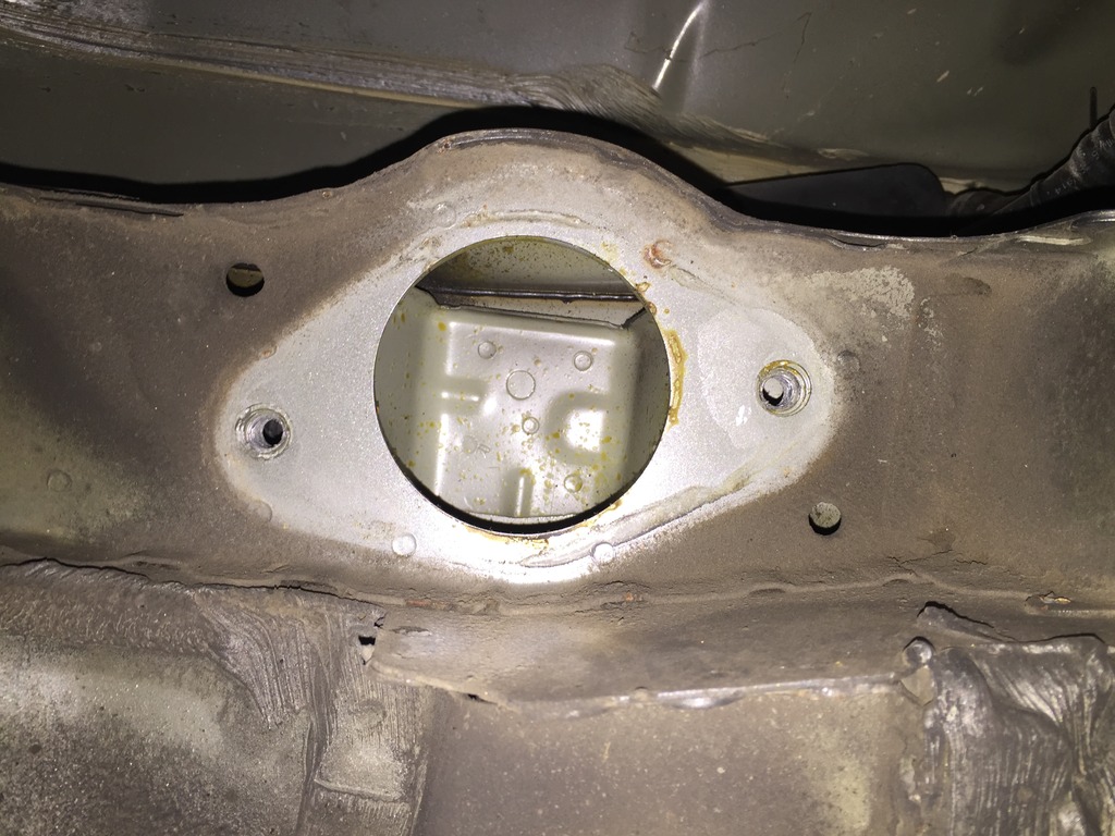
Then, time to drill the shock towers for the extended adjusters. Figured out what size I needed, scouted a hole location, was pretty sure it would emerge at a good place above, and drilled a pilot hole. When I was sure the location was right, I expanded it with a couple of step drills, until it was just large enough to pass the top knob of the adjuster through.
Click the image to open in full size.

The long rear brake hard lines were badly corroded.
Click the image to open in full size.
I had salvaged the ones off the old car, which were like new. It’s a pain, but I swapped them while I was at it. Much better, and one less thing to worry about later.

Hung the fresh subframe, and built the new suspension piece by piece. Set the new adjustable control arms (my new lowers) to the same length as the old ones, then adjusted the old ones to match the length of the OEM upper arms. Used copious amounts of anti-seize on everything. Measured the position of the headlight adjuster sensor on the old left upper control arm, and mounted the bracket on the new arm at the right spot.

Really love how the whole thing looks, especially the painted GP trailing arms.
Click the image to open in full size.

It’s basically done. A little more cleanup to do on cables, brake lines, wheel well liners, battery cable, etc. another day.
Click the image to open in full size.

Makes my adjuster stand at attention.
Click the image to open in full size.

Trailing arms and stuff

About 4 hours today, getting ready to build the rear suspension.

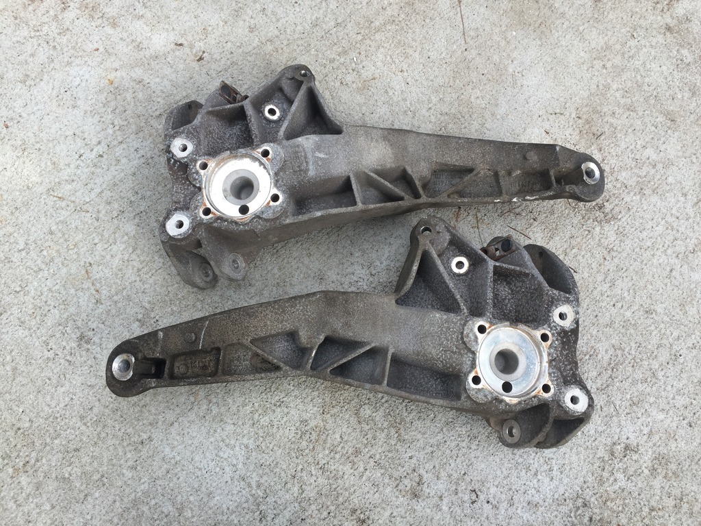
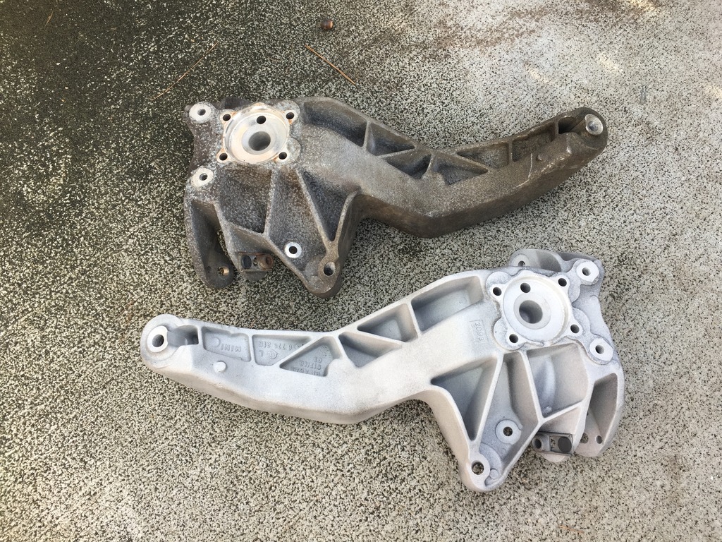
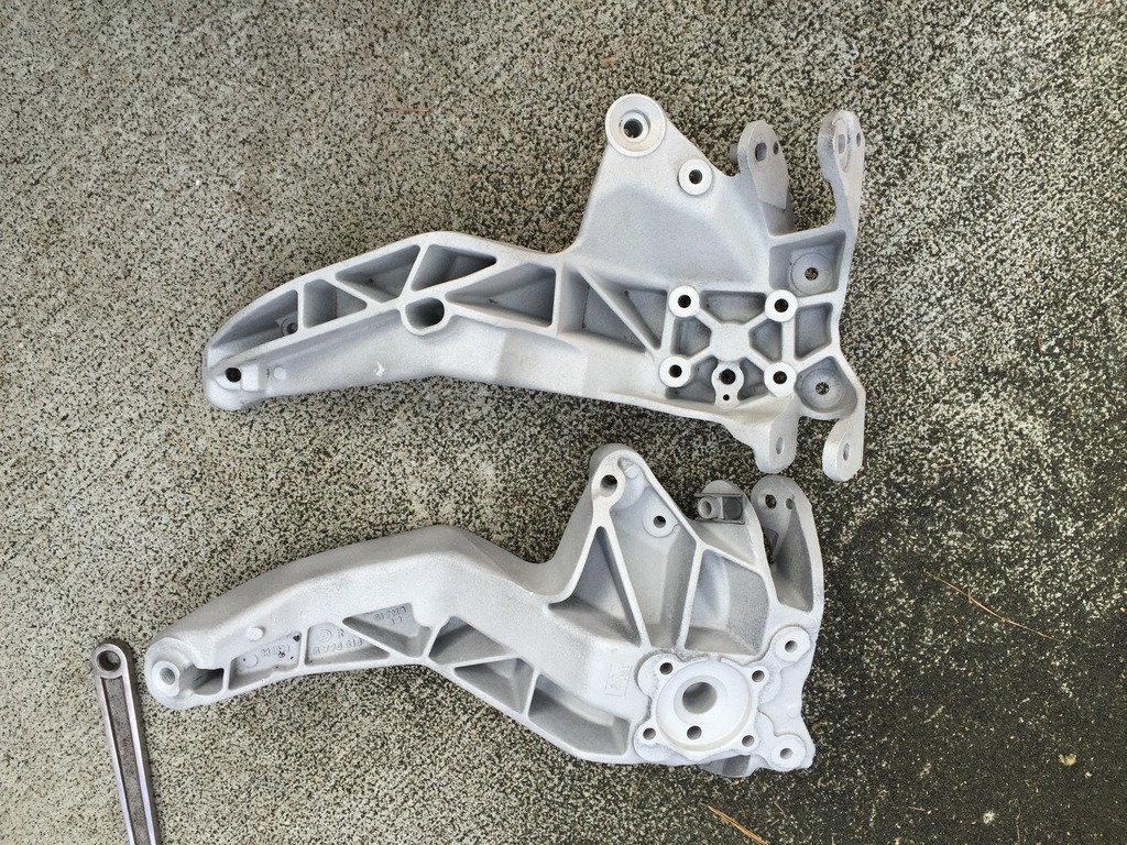
These are the trailing arms off GP0769. Remember, that car was driven several winters in the snow belt… and it shows.
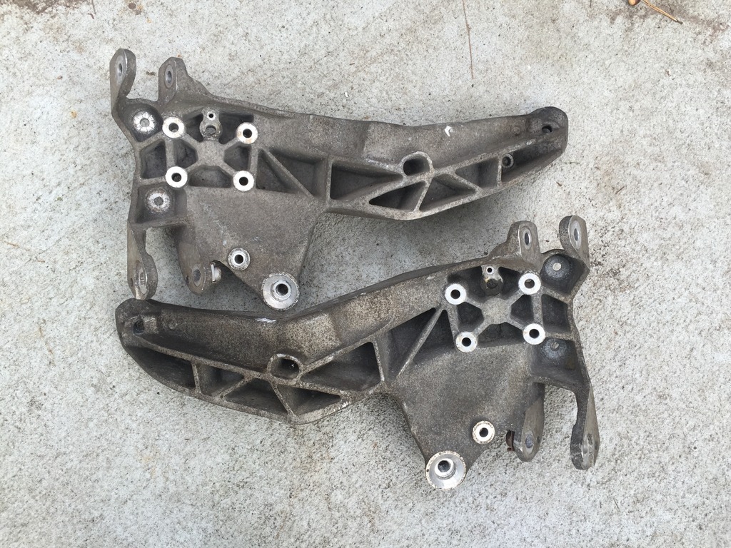
Click the image to open in full size.

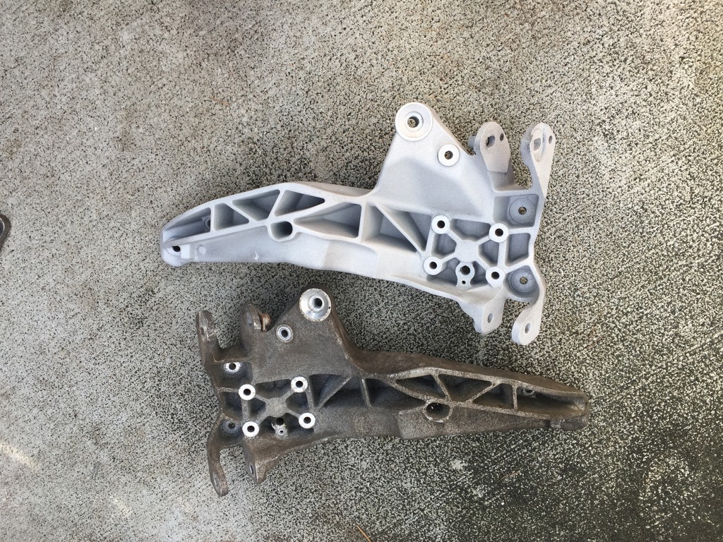
Several of the steel-to-aluminum bolts were seized when I pulled these off the GP. One was seized so completely, I wrung off the shaft of one the big, strong pivot bolts before it would budge. Wellzy drilled it out for me, picked the remaining steel threads out of the arm, and saved the threads. So now they’re functionally OK, but they looked like crap, tons of corrosion.

So… BLASTED THEM!
Click the image to open in full size.

It’s amazing how nicely they cleaned up.

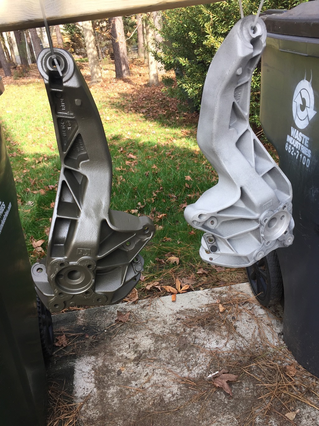
I don’t want them to get gross again, so I’m not going to leave them as bare aluminum. I had considered powder coating them, but don’t want to risk the heat weakening the already-weakened threads. So I decided to paint them instead. Picked a nice, neutral, “cast iron” color. Because there will be lots of other color elements in the rear suspension, the arms don’t need to be flashy.
Click the image to open in full size.

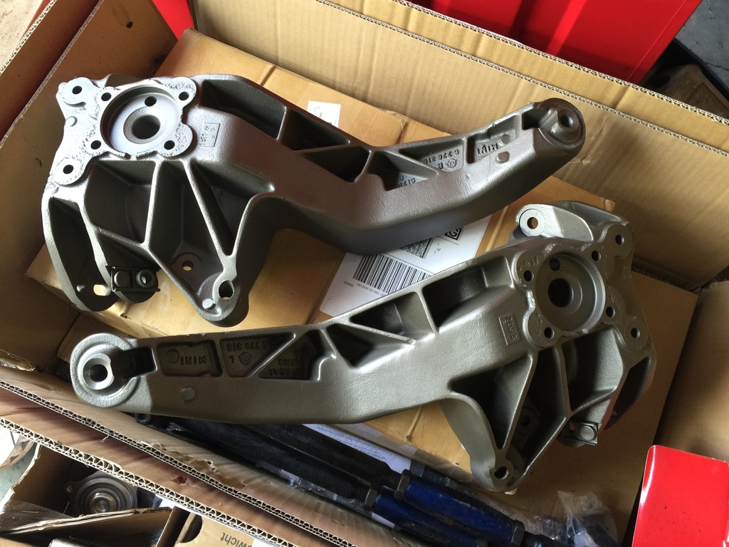
Five coats (two cans) of Duplicolor “Ceramic” engine enamel. This stuff is really nice, dries fast and makes a smooth, hard finish that should clean up easily and should be pretty durable.
Click the image to open in full size.

They actually turned out better than I imagined.

I also degreased the rear subframe from Blimey (which is much less rusty than the one on the new shell), scraped and scuffed a few small rust patches, and sprayed them with rust converter. Tomorrow I’ll cover them with chassis paint.

Also scraped, scuffed, and converted rust on the shell’s front subframe, and on the underside of the shell where the cage A-pillar plates were welded in. Tomorrow I’ll spot-paint the subframe, and will apply rust encapsulating undercoat where needed.

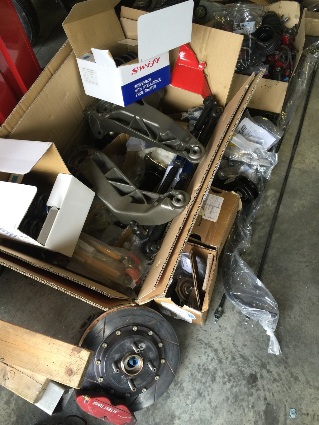
I sorted out all my suspension stuff, to get ready for the build tomorrow.
Click the image to open in full size.

I also assembled my coilovers… pics of those tomorrow!

And, this came…
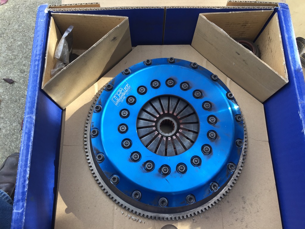
Click the image to open in full size.

Very slightly used OS Giken STR clutch. From Ben Chaltraw’s RMW Turbo Monster. He put this on to break in his new motor, then decided to go full retard on the turbo kit and upgraded to a dual disk OSG clutch to carry much more torque. This is almost new, but I still had Colin get the friction surfaces cut so it will be like-new when I install.

So I’ll have a slightly used Cluchtmasters FX200 for sale soon. 

Starting to look like a car

Spent a few hours today getting the front interior mostly finished. Installed shifter, e-brake covers, DSC yaw sensor, anti-submarine straps, and sat the seats in place.
Click the image to open in full size.

Yes, I sat inside and made racecar sounds.
Click the image to open in full size.

Played around with head unit positioning for a little while. Still some work to do on that.

More dash fitting

Just a couple of hours yesterday, got the right parcel shelf fitted. LOTS of trimming required, but will be invisible when it’s all done – I’ll line the shelf with felt, probably.

Click the image to open in full size.

Confirmed that the stereo head unit will not fit in there, with the cage knee bar in the way. Need to find another home for it. I ordered an under-dash mount and will see how that works hanging on the bottom of the right side parcel shelf.

Today, spent a couple of hours this morning cleaning out the car and fitting the carpet. Just needed to remove some foam padding from the back, didn’t have to cut it to fit around the front cage pillars.

This afternoon, installed the side sill covers. They required much fitting, but look good now that they’re done. Also installed accelerator and dead pedals. Starting to look more like a car…

Click the image to open in full size.

Hope to substantially complete the front interior tomorrow, then can get started on the suspension and engine bay.

Sometimes, little stuff eats lots of time

Had hoped to get the interior mostly finished up today. Instead, the steering column was a 2 hour job instead of a 15 minute job.

Determined that Blimey’s column was buggered, after getting it mostly installed. So had to swap the key cylinder and steering angle sensor to the GP column and install it, and still had to fight it a bit. Ultimately better, because (a) Blimey’s column was for an automatic and (b) the GP column has half the mileage and (b) it’s another GP part the I can use.

Anyway, that ate my afternoon. I’ll play more tomorrow, maybe.
Fitting the dash

Spent a couple of hours finishing up the dash.

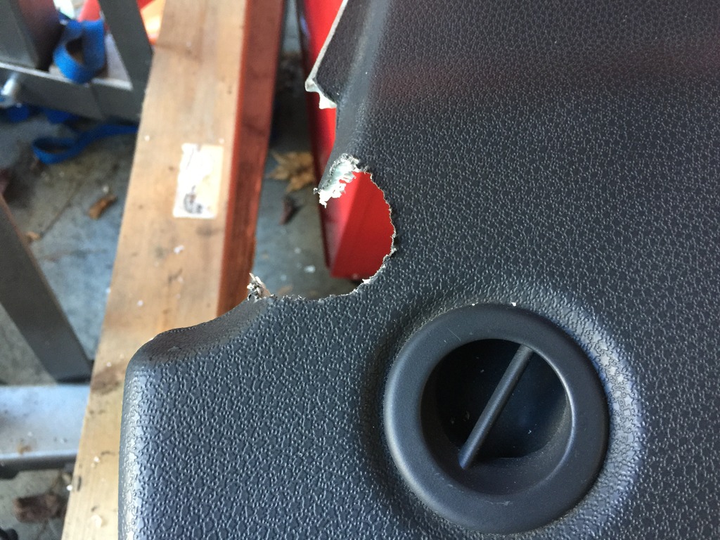
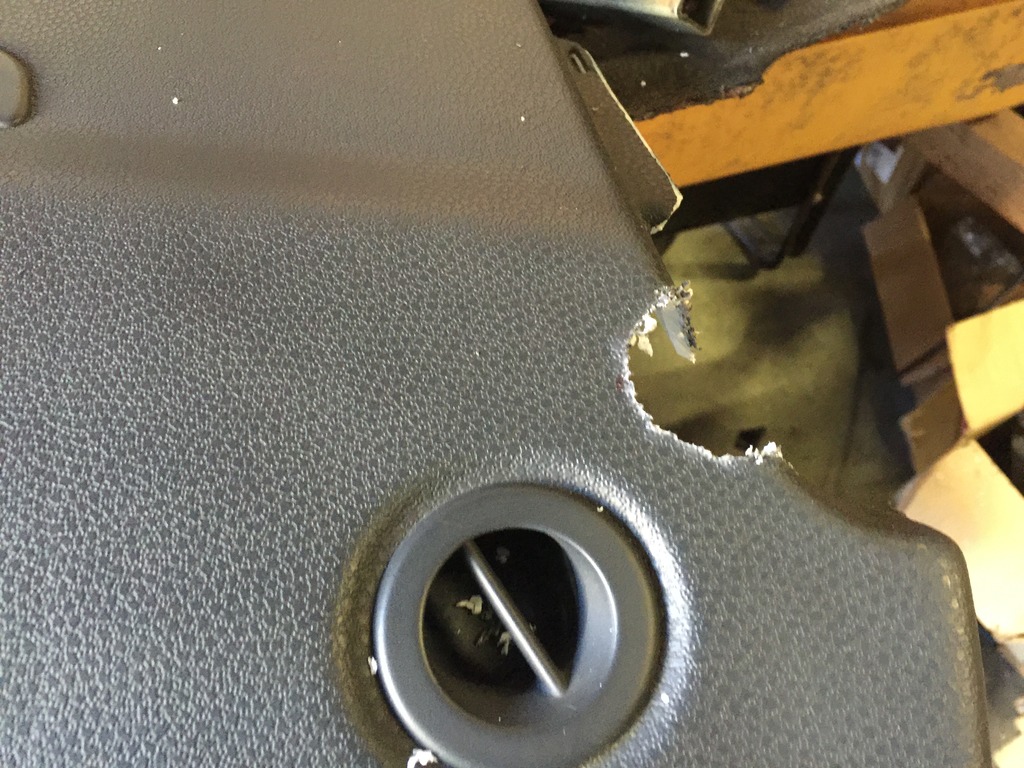
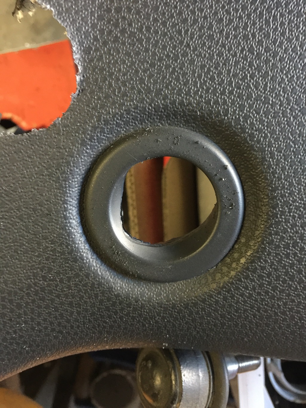
Used the sacrificial dash pad to figure out how to minimize material removal this time. Measure 42 times, and cut once (hopefully)… Really only needed a single 1.75″ hole bored in each side, at a very precise spot. I intentionally made it a bit on the tight side, easier to remove material if needed, than add it back.
Click the image to open in full size.

The trick is, getting the fatter parts forward of the cage past the cage A-pillars. I don’t know how others have done this, but I tested doing “origami” on the sacrificial pad, and it works. So I did that again.

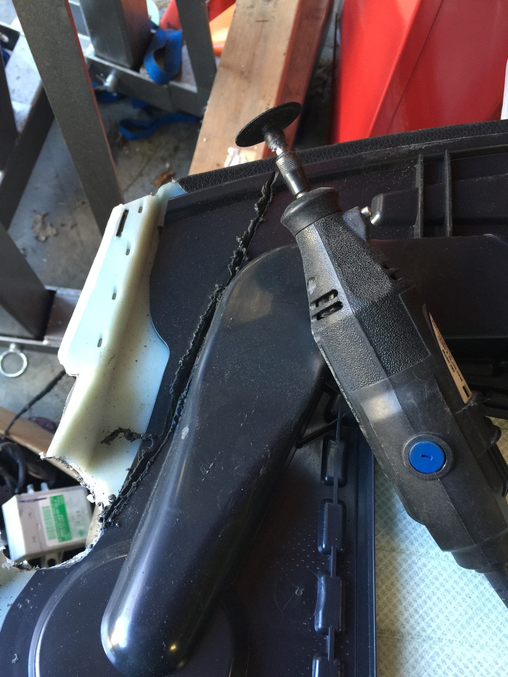
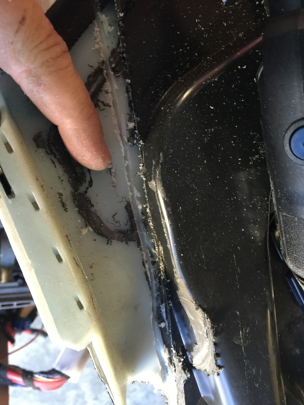
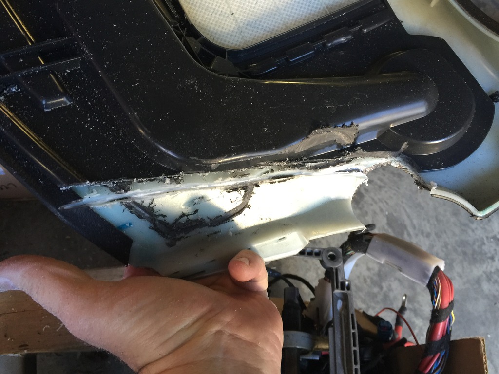
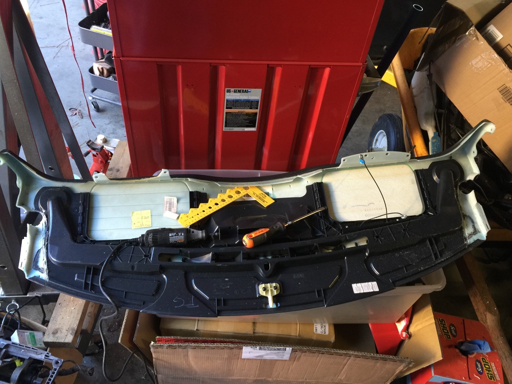
First, remove the extra duct layer on the bottom of the dash pad. I used a Dremel tool with cutoff wheel.
Click the image to open in full size.

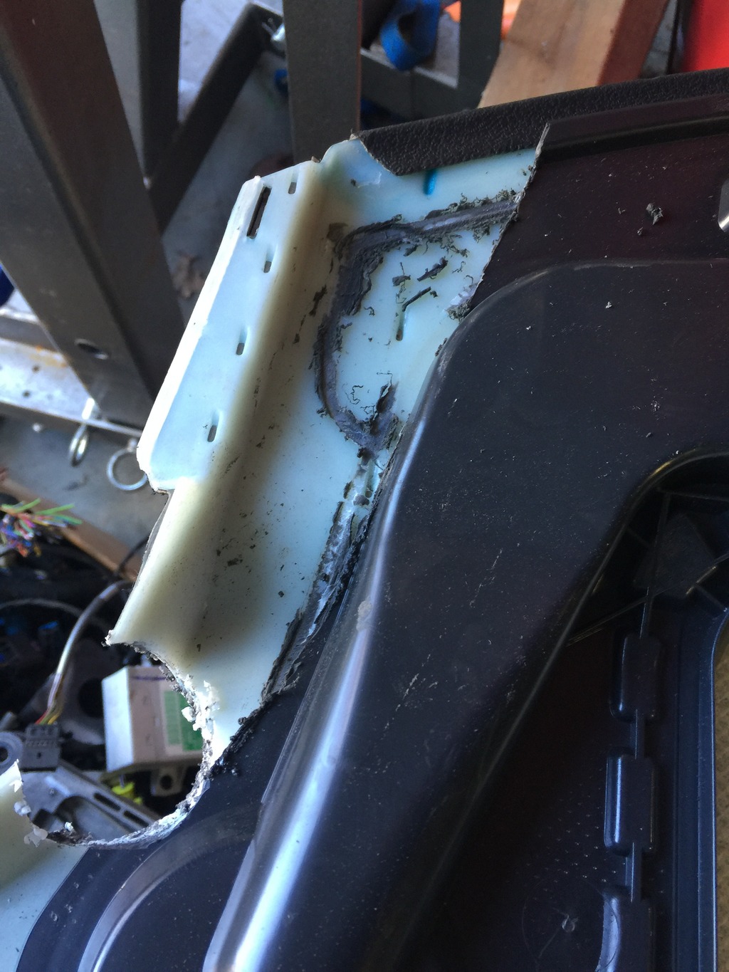
Then, VERY CAREFULLY score the plastic dash pad layer, about 3/4 of the way through the plastic. DO THIS VERY CAREFULLY because it’s easy to plunge too deep… then you’ve penetrated the vinyl dash cover on the other side, and ruined the pad. I was careful and didn’t mess up on either pad. Start at the deepest part of the hole, and angle toward the middle of the pad as you go to the front edge. You want a fairly straight cut.
Click the image to open in full size.

May take a bit of trial and error to get deep enough. Once you do, you can fold the new “wing” you’ve made upward (as the pad faces up). It may snap the remaining plastic, but the vinyl will remain intact.
Click the image to open in full size.

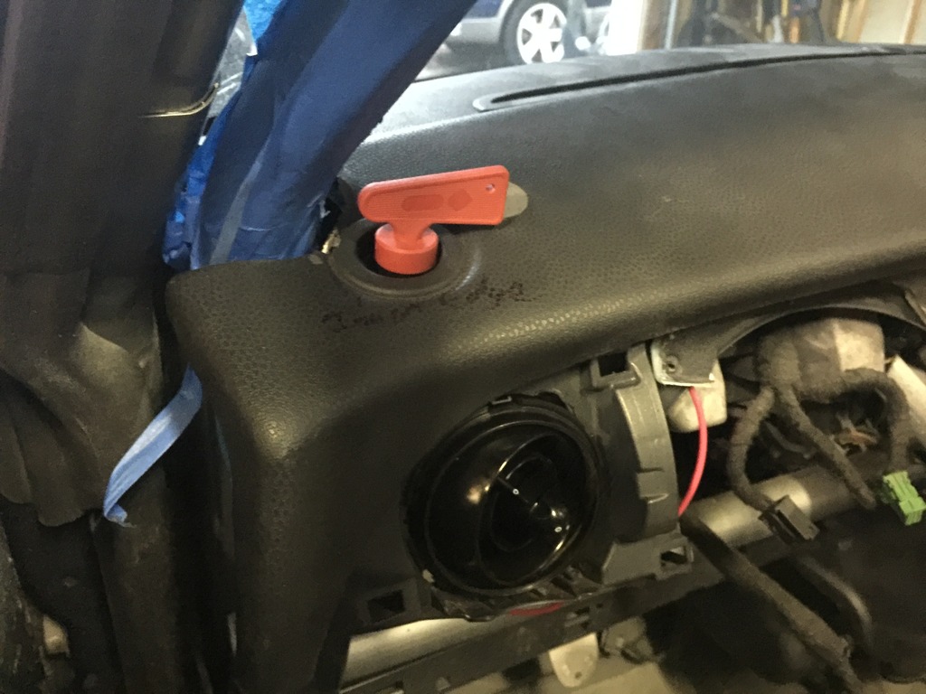
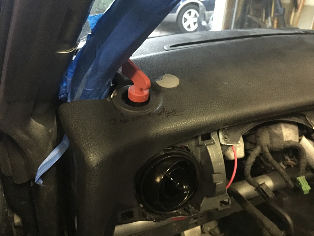
I also needed to remove more of the black duct plastic behind the side window defogger vent, and open up the vent hole for my kill switch.
Click the image to open in full size.

Then, time to install. It was VERY tight this time, very hard to get everything lined up, get the centering pin in place, and getting the pad to slide/snap down into position… but finally did. I could have drilled the holes a few mm inward and it would have been a little easier. But now that it’s in, it’s good that it’s tight.
Click the image to open in full size.

Once in place, fold the wings back down and install the modified A-pillar trim. Done. The wrinkles in the dash pad should flatten out once the pad has warmed up in the sun a few times.
Click the image to open in full size.

Decided to go ahead and make the dash a little prettier… It’s starting to look like something! Motivates me to keep working.
Click the image to open in full size.

When “oh that would be a neat feature” turns into a huge project

OK… that took all damn day….

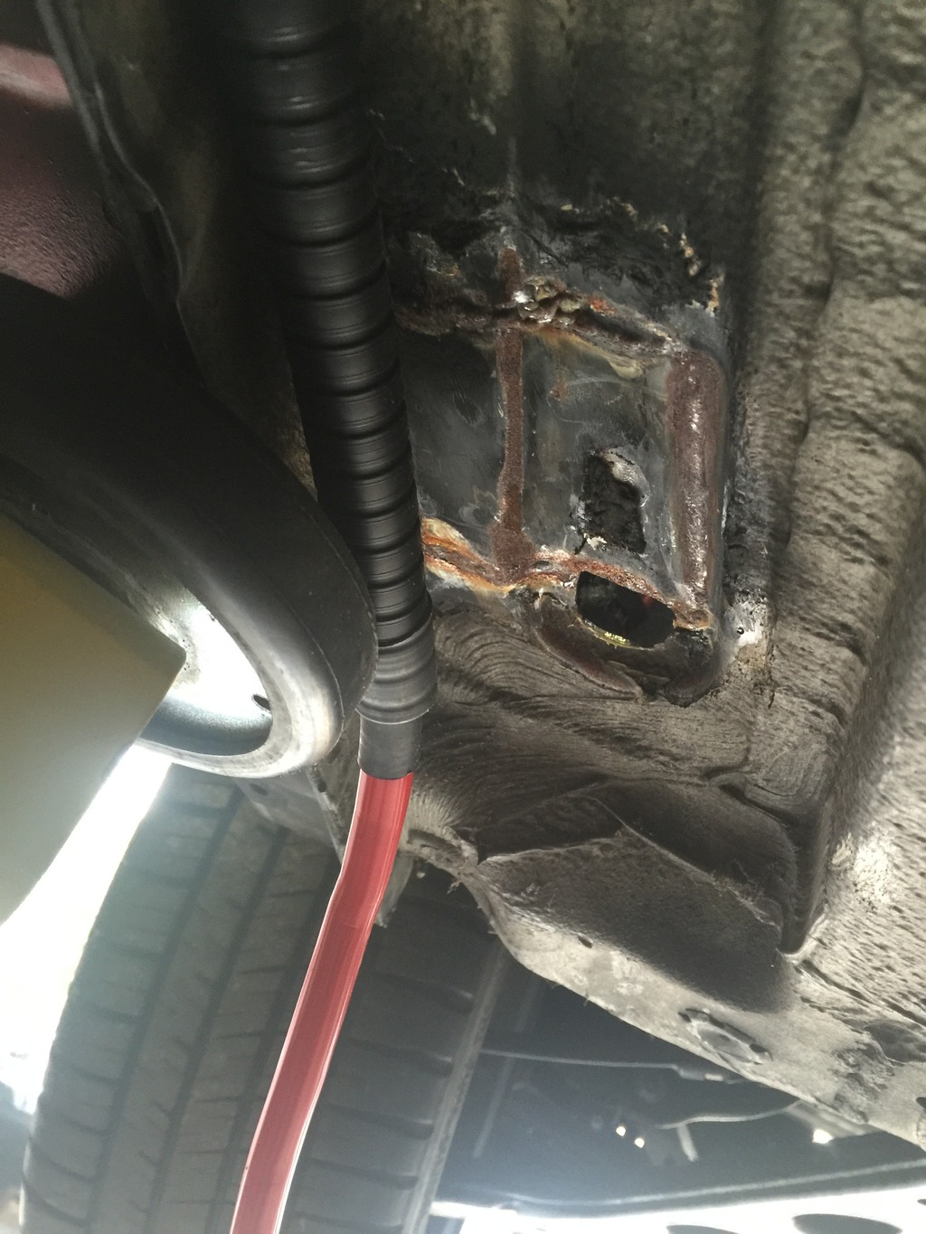
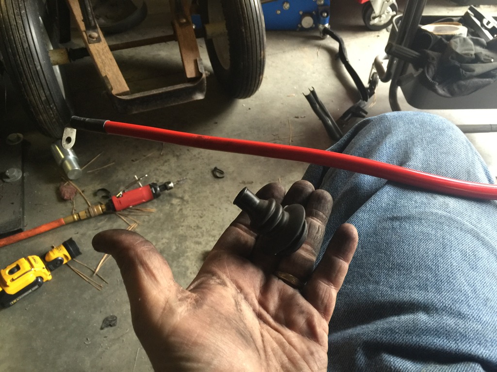
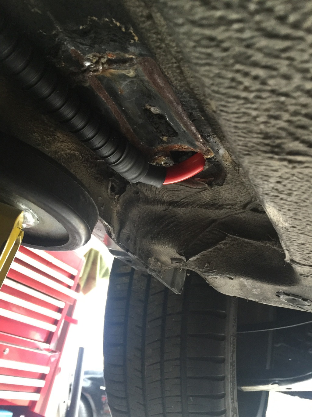
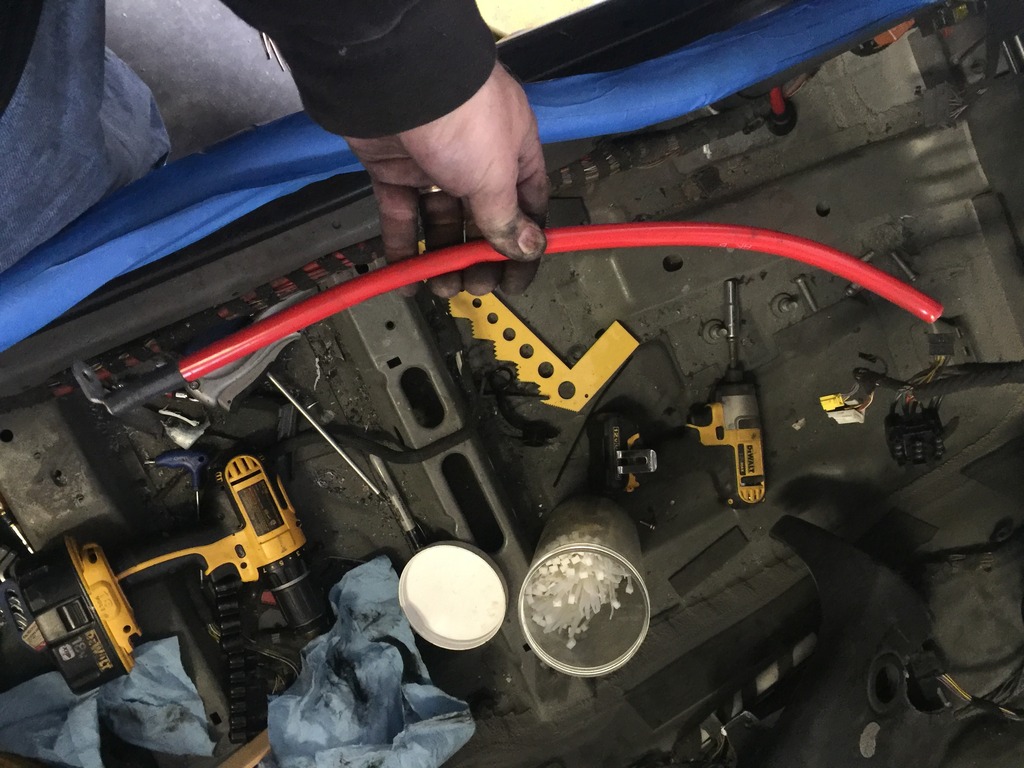
Ran the new battery cable. Instead of going up the front left wheel well, I went through this hole just forward of my front cage plate. Enlarged the hole a little and used a factory grommet from an old harness.
Click the image to open in full size.

Yeah, I need to add some undercoating where the cage plates were welded in.

Cut about 2′ off this really expensive new battery cable.
Click the image to open in full size.

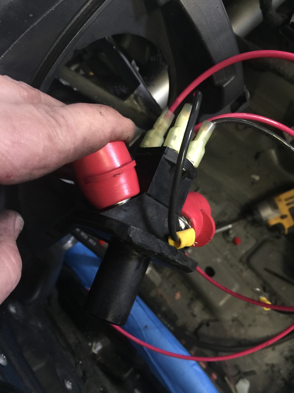
Wired the switch per the instructions. Required a couple of trips to the hardware store and one trip to the auto parts store, for connectors, 12g wire, mounting hardware, and some additional 2g battery cable.
Click the image to open in full size.

This switch does three things: cuts the main line from the battery, kills the main ignition line (the “run” signal that powers fuse 34), and shorts the alternator through a large resistor to ground, to prevent a damaging voltage spike when the battery connection is cut. That’s why it has so many wires and terminals.

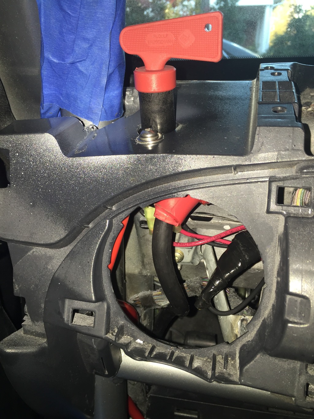
Installed the switch in the dash frame. It’s tight in there, but it works. Used insulating boots on the terminals to ensure no shorts. I’m also going to add a rubber sheet between the switch terminals and the metal dash structure, just to be extra careful.
Click the image to open in full size.

Had to cut some stuff off the back of the (now nonfunctional) vent, and grind out the dash frame to allow it to rotate 90 degrees, to increase clearance behind it for the wiring. But will look good when done. Switch in the “on” position…
Click the image to open in full size.

And the “off” position…
Click the image to open in full size.

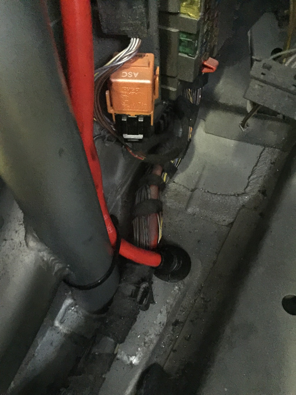
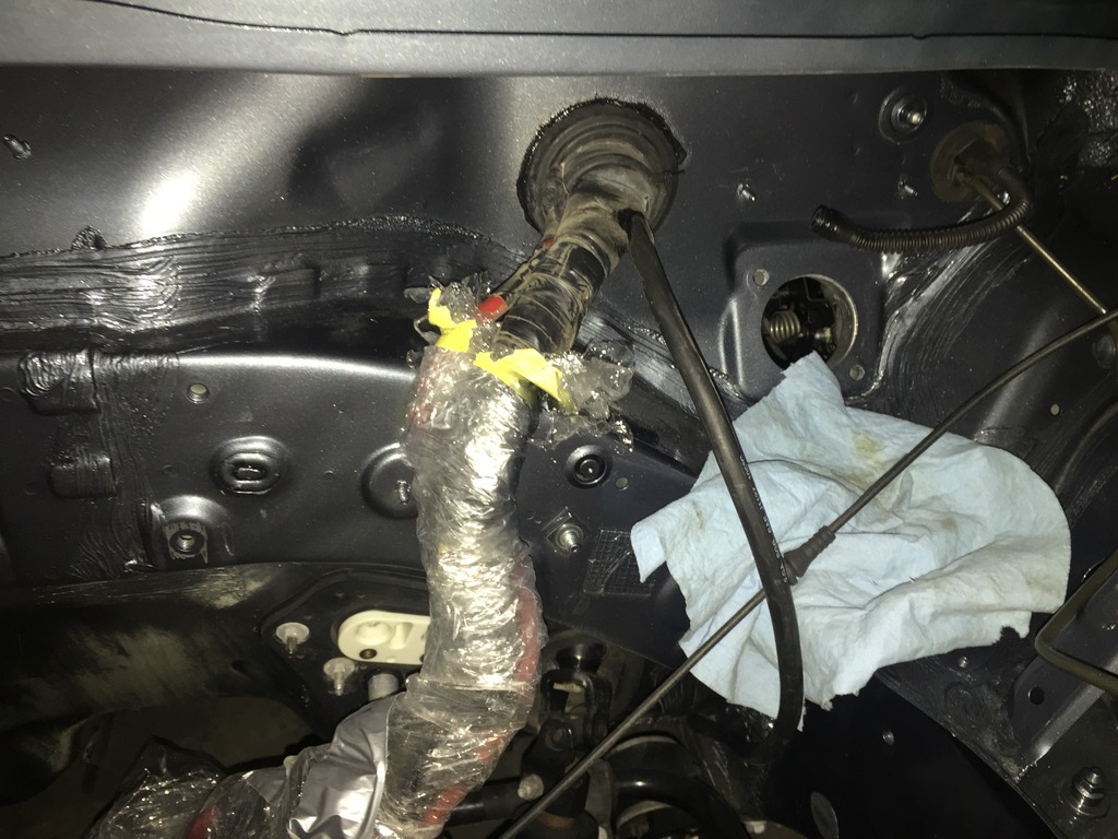
Routed the new battery cable from the switch, through the firewall wiring harness grommet. Just need to re-seal it.
Click the image to open in full size.

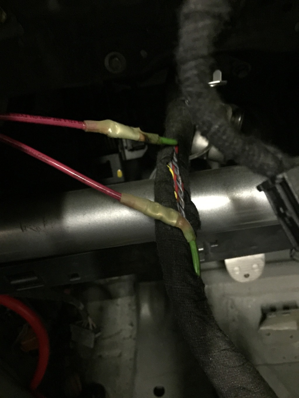
Took me a while, but I finally found the right wiring diagrams and confirmed that the green ignition wire is the one I need to interrupt. Done.
Click the image to open in full size.